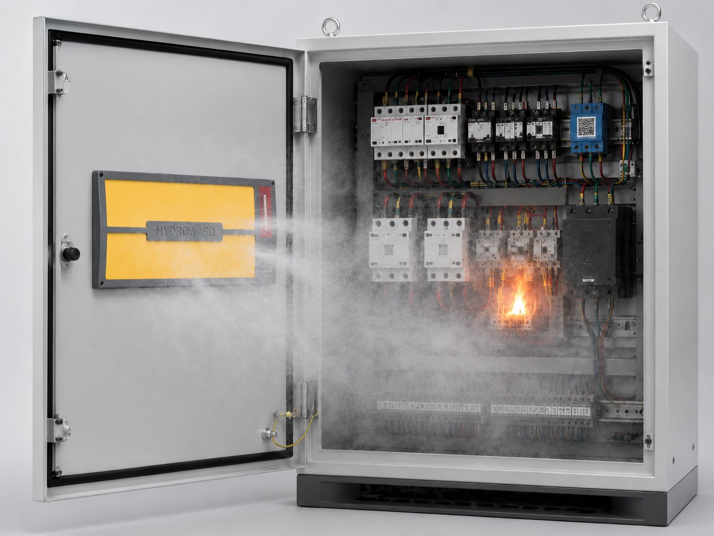
High-performance solid-state active fire suppression patch for precision equipment, enclosed spaces, and renewable energy. Microcapsule-sealed FK-5-1-12, passive 140°C activation, zero residue, replaceable core design.
140°C
Activation
Passive
No Power
Replaceable
Reusable
Zero ODP
Eco-Friendly
CORE ADVANTAGES
Six Core Advantages
Microcapsule Sealing
FK-5-1-12 extinguishing agent sealed in microcapsules within the patch substrate. Stable at room temperature, 10+ year storage life.
Passive Activation
Purely physical mechanism, 140°C auto-response. No power, sensors, or control system required.
Replaceable Core
After discharge, only the core needs replacement. Housing is reusable, significantly reducing maintenance cost.
Clean Suppression
FK-5-1-12 with ODP=0, GWP=1. No residue, non-conductive, non-corrosive to precision equipment.
Smart Tracing
Three-stage color indicators (80/100/120°C) show the maximum temperature the patch has experienced.
PFCS Protective Sheets: Inside the Composite Architecture
The PFCS protective sheet is a multi-layer composite that encapsulates a heat-reactive inner layer between a durable carrier substrate and a top surface engineered for the target environment. When surface temperature exceeds a defined threshold, the inner layer expands and forms an insulating char, choking off oxygen from any nascent arcing or thermal event at the surface it protects. The architectural choice to use a multi-layer composite rather than a monolithic sheet has two consequences. First, the protective layer remains mechanically stable well below activation temperature, which means routine operations are unaffected. Second, the activation itself is sharply bounded: the layer either deploys under its designed stimulus or remains dormant, with no partial-state ambiguity. Customers evaluating PFCS for retrofits often visit the pilot factory to observe this activation with their own panels, which is the most direct way to align expectation with engineering reality.
Selecting Coverage Areas and Wiring Strategies
PFCS sheet coverage is not a uniform recommendation. Critical junction zones, exposed busbars, and surfaces adjacent to terminations are the highest-priority placements; large flat surfaces with limited exposure can usually wait for the next retrofit cycle. CHILION's deployment guide walks the installer through a coverage selection logic that takes cabinet geometry, fault-current rating, and ambient temperature range as inputs and produces a coverage map. Installation crews who follow this process generally complete the application at a faster pace than crews who treat coverage as a uniform spreading task, because the high-priority zones are demarcated ahead of time. Wiring strategies inside a cabinet also matter: shielded cabling routed through the coverage zones can interact with the PFCS layer in ways that the engineering team reviews during design review.
Calibration and measurement discipline: Field Practice for Product Afcp
Calibration and measurement discipline is the foundation of credible alert output. Sensors that drift produce false alarms that erode operator trust; sensors that are not recalibrated produce missed events. Our deployment methodology specifies calibration intervals that respect the sensor class and the operating environment, with the discipline embedded in the maintenance record rather than left to the operator's initiative.
How often should sensors be calibrated?
This section reflects the deployment practice we've refined across the installed base. Customers who want more detail on the specific topic for their site can request a focused engagement through the contact form on our contact page.
Regulatory landscape and standards: Field Practice for Product Afcp
The regulatory landscape that applies to electrical-safety equipment continues to evolve, with periodic updates to IEC, GB, and UL regimes and a corresponding need for the deployment to remain audit-ready across those updates. Our deployment documentation maps the current configuration to the applicable standards with version tags, so a future audit can quickly verify that the deployment still satisfies the regime in force at the time of inspection.
Which standards apply to a typical deployment?
This section reflects the deployment practice we've refined across the installed base. Customers who want more detail on the specific topic for their site can request a focused engagement through the contact form on our contact page.
Field feedback and product roadmap: Field Practice for Product Afcp
Field feedback from across our installed base flows into our quarterly product-development cycle. Customers who participate in our field-feedback program see their observations reflected in subsequent firmware revisions, configuration improvements, and accessories. This is the loop that distinguishes a vendor with an installed base from a vendor with a marketing channel: the latter collects feedback into a presentation, the former collects feedback into a roadmap.
How is field feedback used in product development?
This section reflects the deployment practice we've refined across the installed base. Customers who want more detail on the specific topic for their site can request a focused engagement through the contact form on our contact page.
Calibration and measurement discipline: Field Practice for Product Afcp
Calibration and measurement discipline is the foundation of credible alert output. Sensors that drift produce false alarms that erode operator trust; sensors that are not recalibrated produce missed events. Our deployment methodology specifies calibration intervals that respect the sensor class and the operating environment, with the discipline embedded in the maintenance record rather than left to the operator's initiative.
How often should sensors be calibrated?
This section reflects the deployment practice we've refined across the installed base. Customers who want more detail on the specific topic for their site can request a focused engagement through the contact form on our contact page.
Regulatory landscape and standards: Field Practice for Product Afcp
The regulatory landscape that applies to electrical-safety equipment continues to evolve, with periodic updates to IEC, GB, and UL regimes and a corresponding need for the deployment to remain audit-ready across those updates. Our deployment documentation maps the current configuration to the applicable standards with version tags, so a future audit can quickly verify that the deployment still satisfies the regime in force at the time of inspection.
Which standards apply to a typical deployment?
This section reflects the deployment practice we've refined across the installed base. Customers who want more detail on the specific topic for their site can request a focused engagement through the contact form on our contact page.
Calibration and measurement discipline: Field Practice for Product Afcp
Calibration and measurement discipline is the foundation of credible alert output. Sensors that drift produce false alarms that erode operator trust; sensors that are not recalibrated produce missed events. Our deployment methodology specifies calibration intervals that respect the sensor class and the operating environment, with the discipline embedded in the maintenance record rather than left to the operator's initiative.
How often should sensors be calibrated?
This section reflects the deployment practice we've refined across the installed base. Customers who want more detail on the specific topic for their site can request a focused engagement through the contact form on our contact page.
Calibration and measurement discipline: Field Practice for Product Afcp
Calibration and measurement discipline is the foundation of credible alert output. Sensors that drift produce false alarms that erode operator trust; sensors that are not recalibrated produce missed events. Our deployment methodology specifies calibration intervals that respect the sensor class and the operating environment, with the discipline embedded in the maintenance record rather than left to the operator's initiative.
How often should sensors be calibrated?
This section reflects the deployment practice we've refined across the installed base. Customers who want more detail on the specific topic for their site can request a focused engagement through the contact form on our contact page.
Frequently Asked Questions
How long does PFCS remain active once installed?
Does PFCS installation require cabinet shutdown?
Most retrofits can be performed with the cabinet de-energized and isolated for the duration of the work, with surrounding circuits remaining live.
Is there a sample coverage layout available?
Yes, sample layouts are available for the most common cabinet geometries in the downloads section.
What testing standards apply?
PFCS components are tested against applicable IEC and GB standards for thermal barrier materials used inside energized enclosures.